Monday, 4 April 2016

Colour 3D Printing

Colour matching in 3D printing is not quite the same as colour matching in traditional reprographics. Different materials reflect light differently and three dimensional forms create shadows producing variations in tone of colour that are not seen on flat images.

There are many factors that affect 3D printing in colour: reflectivity, translucency, surface texture, tonality and saturation are just some of them. 

As is often the case, it really depends what you are trying to achieve. The ability to produce skin tones or very light and washed out colours are often more desirable over fully saturated bright colours. 

At Lee 3D, we print using the ProJet 660 printer, made by 3D Systems, which prints CMYK coloured binder onto a white substrate powder. This offers a wide range of colour and tonal qualities. 
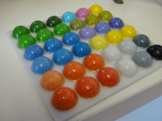

Sample parts made on ProJet 660
Gloss finish can intensify brighter colour


Parts made on ProJet 660
Light and subtle tones

While we have never claimed to match Pantone or RAL colours, we can get quite close as shown in the image below. 

The reality of these machines is that the whiteness of the powder varies slightly between machines and if printheads are not properly aligned and parts are not finished meticulously then they can produce inconsistent part quality. But by attending to details, it is possible to make high quality colour 3D prints using this system.


Matching colour to the RAL paint system
It is possible to get something pretty close with most colours

There are two main alternatives to the ProJet for colour printing. These are the MCor and Stratasys machines. The MCor machine has limitations on the geometry that can be produced, while the Stratasys offerings are significantly more expensive machines to buy and to run. In particular, it is usually not possible to print hollow parts on these machines as they need a solid platform of material supporting all parts of the model as it prints. A third colour printer looms in the background in the form of the HP offering, but this appears to print on a black substrate precluding pale and pastel shades. 

Of these, the newly released Stratasys J750 printer may prove to be the most accurate colour printer ever made. The parts are likely to be highly accurate and can have multiple material characteristics as well as colours. But lower cost and the achievable quality on a well made ProJet part may continue to make this the machine of choice for much colour work for years to come.


Colour 3D prints made on ProJet 660


For more information about Lee 3D colour printing visit http://www.lee3d.co.uk


Thursday, 31 March 2016

Exporting for 3D print

The subject of this blog is one of those topics that rarely gets covered in depth. In practice I am frequently telling customers to move their data to the origin before exporting for 3D print. But why is this? 

Many BIM, CAD and 3D modelling programs have a very large drawing space. An example of why this would be useful is when designing a very large structure like a road or railway. Similarly a large coordinate space allows buildings to be designed at their correct location in relation to a city grid.

When exporting 3D models for applications such as 3D printing a problem can occur causing the exported data to become deformed as shown in the image below. 

Bad STL export of sphere from Rhino when
deliberately modelling far from origin


The problem seems to be that most 3D modelling programs are based on geometric modelling Kernels such as ACIS or Parasolid. These work fine when close to the origin but lose accuracy outside of the kernel's modelling space. 

Confusingly many of the applications functionality is unaffected by modelling outside the kernels modelling space but certain functions either fail completely or result in degraded data.

In MicroStation for example the coordinate system (Working Area) will go well beyond a million km from the origin but the Solids Area is only a 4.2km cube. The 4.2km limit being set by the Parasolid modelling kernel used in MicroStation. When you draw more than 2.1km from the origin the lower resolution may not be immediately apparent but may manifest downstream, such as when you export to STL etc.

This is not a problem restricted to MicroStation. It is a problem with most 3D modelling packages. As a consequence it is always best practice to model near the origin whenever possible. 


Modern Architectural Design Tools Timeline

The following timeline places various architectural design tools by date. The purpose for this record was to create a context in which to view 3D printing as a design tool. From this point of view, today (2016) it is clear that the use of 3D printing in architecture is still very new. Even though early adopters were employing SLS and SLA printing for architectural model making in the 1990s and plaster-based printing from the 2000s these are still few and far between. 

Four buildings have been added to the timeline to act as a reference. These are somewhat arbitrary and do not necessarily represent precedents in use of technology. 

Each of the buildings shown relate in some way to the story of computing in architecture, not least the Lloyds building, the design of which commenced before any of the CAD packages that we know today. The Lloyds building was designed and built in the period that saw the appearance of the first personal computers. This led to a change in the way buildings are used and serviced and consequently changed the form of the buildings themselves. The affect of computing on architecture is undeniable but not always obvious. New design tools change the way architects work but the affect of design tools on the design of the buildings produced is sometimes less easy to identify.

There have been a great many pioneers of architectural design tools. Many tools have been developed and for one reason or other they have been abandoned or superseded.  It is worth making the observation that there is often little inclination to share detailed information on active design projects. Once buildings are complete and considerations of confidentiality have past these details fade from memory as focus switches to new challenges. Therefore much pioneering work is lost to public record. This timeline is admittedly only the bare bones of the story. 


1928 Tintenkuli nibless drawing pen (precursor to Rotring Rapidograph)

1953 Rotring Rapidograph drawing pen

1953 IBM 650 series of computers

1956 First computer keyboard

1957 Jorn Utzon wins international competition to design Sydney Opera House. Ove Arup & Partners engaged as engineers.


Detalle interior ópera Sydney
Sydney Opera House detail
Image by Leithcote / Antony Oliver (Flickr)
via Wikimedia Commons


1959 Letraset founded - manually applied lettering system

1959 Calcomp 565 pen plotter 

1960 DEC release first Mini Computer, the PDP-1, priced between $125,000 and $250,000. This computer was used to play 'Spacewar', the first digital screen game.


Spacewar running on PDP-1
Image Joi Ito via Wikimedia Commons


1962 Douglas Englebart envisions BIM in "Augmenting Human Intellect". He anticipates 
object based design, parametric manipulation and a relational database

1963 Ivan Sutherland writes Sketchpad considered to be the ancestor of modern CAD programs

1963 First Pantone Matching System Printers Edition

1963 First computer mouse, invented by Douglas Englebert

1965 After 8 years work on Sydney Opera House Tim Rice and Tony Cramm write a program from scratch, they run it at night borrowing time on an Australian General Electric computer to calculate positions of pre-cast segments. 


Sydney Opera House construction 1968
Sydney Opera House 1968
Image by PhillipC (Flickr) 
via Wikimedia Commons

1968 Conference 'Computer Graphics in Architecture and Design' Yale University

1969 Appalachian Conference, led by SOM at an IBM research facility. Out of this was formed the SOM, Computer Group

1973 Sydney Opera House opens

1974 Intergraph IGDS, precursor to MicroStation

1975 DRAW2D, SOM Computer Group

1977 DRAW3D, SOM Computer Group

 1977 Really Universal Computer Aided Production System (RUCAPS) sold through GMW Computers Ltd (from GMW Architects)

1978 Richard Rogers begins work on Lloyd's Building

1981 IBM launches first Personal Computer running Microsoft MS DOS 1.0

1982 AutoCAD 1.0

1982 Catia 1.0

1982 Romulus, the first 3D modelling kernel. Later becomes ACIS.

1984 MicroStation 1.0

1984 ArchiCAD 1.0 (named Radar CH for first version only)

1984 First HP LaserJet printer, Apple's LaserWriter followed the following year

1985 MiniCAD 1.0 (later renamed VectorWorks)

1986 Lloyds Building completed


Richard Rogers Partnership, Lloyds Building detail
Image from Oast House Archive via Wikimedia

1987 First commercial SLA 3D printer, SLA-1, made by 3D Systems

1988 STL file format 

1989 First Commercial SLS 3D printer built by DTM (later acquired by 3D Systems)

1989 ACIS 3D modelling kernel

1989 Parasolid 3D modelling kernel

1990 Photoshop 1.0

1992 Magics 1.0 (an STL editor which became the industry standard software for 3D print bureaus.

1993 PDF 1.0

1994 Gehry Technologies founded

1997 First commercial Z Corporation 3D printer, Z402

1997 Foster + Partners begin work on 30 St Mary Axe

1998 Foster + Partners' Specialist Modelling Group formed, 30 St Mary Axe becomes one of their first projects 

1998 Rhinoceros launched

2000 Morphosis buy a ZPrinter from Z Corporation. They are one of the first architectural practices to run a 3D printer in-house.

2000 Revit 1.0

2001 Microstation v8 (file format changes for first time)

2001 Smartgeometry Group formed

2002 Autodesk acquire Revit


2002 AutodDesk whitepaper "Building Information Modelling"

2003 Bentley Systems' Generative Components in Alpha

2003 64-bit processors become available in personal computers

2004 Morphosis begin designing Cooper Union building using 3D printing as part of the design process

2004 Foster + Partners' 30 St Mary Axe completed


Foster + Partners, 30 St Mary Axe
Image by Nevilley via Wikimedia


2005 Launch of Spectrum 510 colour 3D printer by ZCorporation. The increased resolution and build size meant reasonable quality architectural concept models could be printed overnight. 

2008 - ZPrinter 650, replaced for the 510 with slightly larger build 

2008 Great Recession begins

2009 Morphosis's Cooper Union building completed


Morphosis, Cooper Union building
Image by Short Dale via Wikimedia

2012 3D Systems acquires ZCorporation and rebrands the ZPrinter range as ProJet x60


Advertisement:

2016 Digital Craft - 3D Printing for Architectural Design, written by Bryan Ratzlaff and published by Lee 3D. The first book to deal with 3D printing for architectural design as its sole subject.  


Find out more about Digital Craft at http://www.lee3d.co.uk/digitalcraft/


Monday, 29 February 2016

Digital Craft - why we published


Digital Craft - 3D Printing For Architectural Design
Examining techniques for a new mode of craftsmanship


In terms of the entire process of architectural design, modelmaking may appear to have a relatively small part to play. In terms of 3D printing, architectural models are hardly the main focus. So it could be considered that 3D printing of architectural models is a rather niche subject. But now, the intersection of the ancient profession of architecture and the upstart phenomenon that is 3D printing has a book researched, written and published. Lucky 3D printing for architectural design!


1:1000 massing studies

So why was this book published? From a practical point of view, one of the motivations here at Lee 3D was to help and encourage architects to make better and more effective 3D printed models. 

The term '3D printing' can be quite misleading. At one end of the spectrum it may seem just like printing to paper - it's a printer, isn't it? While at the other end, 3D printing or additive manufacturing, is deeply revolutionary and in many ways needs new ways of designing to exploit its capabilities.

The subject of this book though, lies elsewhere. Here is no polemic about revolutionary potential and still no exhortation to just press print. The focus here is not on the printers but rather on what is being printed. This is a realistic book about using a new tool within the conventions of modelmaking. It is a book about the new digital craft of making.


1:100 facade study model

Another good reason for publishing the book became apparent during the initial research phase. Intellectually, the starting point for the project had been the question - to what extent can a style be applied to a standalone 3D printed model? During early conversations with the author it became apparent that models made as part of the design stage are rarely seen outside the architects' studio. As a consequence, scope for sharing of ideas among professionals was limited and that this lack of cross fertilisation inhibited the evolution of 3D printing styles in architectural modelmaking.

Thus, it became an ambition in publishing Digital Craft that the book would spread ideas about 3D printing architectural design models across the profession. That by doing so it gives 3D printing for architectural design a nudge in the right direction.


Digital Craft published February 2016


About the book
Digital Craft can be purchased from Amazon stores in Europe. It should be possible for Amazon to ship to most countries from these stores. 

About the Author
Bryan Ratzlaff is a Canadian architectural designer working in London with five years’ experience in 3D printing for architects. Bryan has a Master of Architecture degree from University of Westminster (RIBA Part II).

About the Publisher
Published by Lee 3D Ltd, a specialist 3D print bureau focussed mainly on the AEC sector. 


Monday, 15 February 2016

Digital Craft - Press Release

FOR IMMEDIATE RELEASE
CONTACT:

George Lee
e-mail: george@lee3d.co.uk
tel: 0207 582 3904

Elevating 3D Print to a Digital Craft
As a global centre for architectural practice, London has a thriving community engaged in 3D printing models for architecture. Bryan Ratzlaff settled in London just as 3D printing was coming to the public’s attention. Five years in and immersed in both 3D printing and architecture, Bryan has written a book (Digital Craft) that will help architects and modelmakers make sense of and begin to master this rapidly evolving medium.

“Bryan’s book has come at a key moment. Everyone has been independently trying things out but little research has been shared.” said George Lee, director of Lee 3D. “Now with this book, the whole industry gets a chance to evaluate the process and then we can begin to raise 3D printed models to another level.”

Digital Craft positions 3D printing in the tradition of architectural modelmaking. Examining the relationship between the architect, the model and the 3D printer. Combining convention with emerging stylistic forms, the book recognises and presents techniques for a new mode of craftsmanship. A digital craft that goes beyond the casual printout and aspires to the fully designed 3D printed object.

The research was based on interviews with leading professionals and illustrated throughout with photographs of real projects. The resulting book is not founded on fanciful claims, but rather on solid industry experience. Digital Craft places responsibility for the look and style of the 3D printed model firmly in the realm of the architect.


© Steffian Bradley Architects,
University College London Hospitals, phase 5


© SPPARC Architecture,
The Music Box


© Lee 3D Ltd
1:100 colour facade study


About the Book
Digital Craft: 3D Printing for Architectural Design
 is published in printed book form in February 2016.


About the Author
Bryan Ratzlaff is a Canadian architectural designer working in London with five years’ experience in 3D printing for architects. Bryan has a Master of Architecture degree from University of Westminster (RIBA Part II).
 
About the Publisher
Published by Lee 3D Ltd, a specialist 3D print bureau focussed mainly on the AEC sector.


Wednesday, 7 October 2015

Another 3D Printing glossary

In writing this glossary I looked through quite a few 3D printing glossaries. Below is a list of words that are or could be commonly used in the world of 3D printing without being specific to any particular print process. I hope that this does not over or under complicate things. 

3D Printing - see Rapid Prototyping 

Additive Manufacturing - see 3D Printing (in fact this usually refers to more industrial applications of 3D printing)

Auto-fix - this is short hand for "I'm naive and I don't mind surprising results!". Always be wary of anything offering to auto-fix your file and if you do see Diffing Tool.

Build Time - Depending on many factors this is how long it take to build a part in the printer. This is not the same as the total time needed to prepare the file and the printer, print the part, post-process the part, package and deliver. 

Diffing Tool - usually a software tool for comparing two pieces of text much loved by programmers for finding bugs. If you carry out a fixing procedure on the whole model it pays to step backwards and forwards to spot unexpected differences between before and after model states.

Error - this is what frequently happens if you do not look after your 3D printer properly or if your printers have just done too much hard work and something eventually breaks.

Faceting - When the triangulation of the print file is visible in the surface of the printed part.

Feature Size - the smallest features that can be physically printed. This can easily become an obsession. Often better to ask at what size a feature becomes clearly visible. There is always a big difference between the minimum size of structural elements and surface relief details.

File Size - There is an optimum level where mesh size is just right for the resolution of the printer. As triangles get increasingly small, files getting increasingly large and time is increasingly wasted. Files for 3D printing rarely need to be more than 20MB.

Hole - gaps in meshes used to define 3D prints. In the same way that holes in skin are bad for you, holes in meshes are bad for 3D prints too.

Layer - almost all 3D prints are created one layer at a time. Layering is often visible on the side walls of a print. Finer layer thickness is often desirable as layering is less evident visually.

Manifold - "in mathematics, a manifold is a topological space that resembles Euclidean space near each point. More precisely, each point of an n-dimensional manifold has a neighbourhood that is homeomorphic to the Euclidean space of dimension n". In 3D printing it means a mesh without holes - sometimes known as watertight.

Meshing - the process of converting a vector or NURBS model (the design file) to a triangulated mesh or shell used for 3D printing.

Normal - surface or triangle direction defining inside from outside of the model.

Post-processing -  This is the part that the manufacturers and resellers keep quite about. Up until this point it all looks pretty straightforward - then the work begins... 3D printing is not vending and alas is nothing like Star Trek's replicators.

Rapid Prototyping - until recently, rapid prototyping was the term used to describe what has come to be known as 3D printing - or additive manufacturing.

Shrinkwrap - often a last resort when fixing a hideously bad file quickly, the shrinkwrap tool in Materialise's famous Magics software really is magic. And like all good magic the shrinkwrap is most powerful when you can't tell its been used.

Support - parts with overhangs need to be supported as they are printed. Powder based systems are self-supporting whereas other printers need to print a support. Removing supports is usually no fun at all.

STL - the stereolithography file format was created so that people could print to the very first commercial 3D printers. It contains triangle coordinates and normal directions but does not contain unit, colour or indeed any other information.

Texture - in colour 3D printing this refers to an image file mapped on to the surface of the mesh containing colour information to be printed. Not to be confused with physical surface texture. Remember you need a colour 3D printer to print image textures.

Watertight - a manifold shell - i.e a part with no holes.

XYZ - cartesian coordinate system used to locate points in (Euclidian) space. Z usually denotes height in 3D printing but this is not always the case with software modellers.


For more information about 3D printing at Lee 3D please visit www.lee3d.co.uk


Wednesday, 1 April 2015

The rise and fall of the ZPrinter?

One outcome of ZCorporation's acquisition by 3D Systems is that we are no longer quite sure what to call the technology we use.

In the beginning, ZCorp's printers were 3 digit numbers prefixed with Z. So Z402, Z406, Z810 began the series and then in 2003 the ZPrinter 310 was released and the ZPrinter was born.

Strangely the next machine to be announced was the Spectrum 510 in 2005. Despite the Spectrum non sequitur, the next machine was the ZPrinter 450 in 2007 followed by the ZPrinter 650 in 2008, precipitating a minor avalanche of ZPrinters in the next couple of years as the increasingly small ZPrinter 350, 250 & 150 arrived.

Then in January 2012 ZCorporation was no more. 3D Systems bought the company and began to absorb it into the 3D Systems brand.  

Despite this and just months after the take over, the last and biggest ZPrinter arrived, the mammoth ZPrinter 850. Almost immediately news came through that the entire range of ZPrinters was to be rebranded as the ProJet x60 range.

What is a ZPrinter?

Briefly ZCorp made 3D printers that printed binding fluid using HP printheads on to a bed of powder.

ZPrinter 310

In the early days ZCorp experimented with different powders for different applications. The early printers like the ZPrinter 310 shown above were flexible, hands on machines. 

Powders for flexible parts and for casting etc. lost out in time to what the company referred to as high performance composite. Essentially plaster of Paris with some modifiers to improve flow, part strength and finish. 

With the 450 the ZPrinter became a more complex machine but one that requires less user intervention.  They made it easier to use, with automated powder handling and a built in post processing unit. The result was that it was a machine optimised for general purpose plaster printing which was what the majority of the users actually wanted.

ZPrinter 450

The automated powder handling of the later ZPrinter range was a great success from a users point of view. While it slowed down various aspects of the 3D printing process, not having plaster powder blowing up in your face when reloading the machines meant this was a small price to pay.

Some of the later ZPrinters have an automatic de-powdering feature. This proved to be something of a gimmick and must have added a significant cost to the price of the machines that featured it for no significant gain except for the marketing brochure. 

So what is the point of all this?

The question remains what do we call this technology? Bringing the ZPrinter into ProJet range and calling it ProJet x60 is really not very helpful for the average user. If I say that I am running ZPrinters most customers know what I am talking about. If I say we are running Projet x60s mostly customers are just baffled. 

Officially the technology used by the Projet x60 printers (ZPrinters) is Color Jet Printing or CJP. This brings the product in line with 3D Systems preoccupation with ProJets "Jetting" stuff. Again no one can remember what CJP stands for and the acronym blends into a background of stand-back jargon.

The thing is the full ProJet range has some great machines and some proper clankers. With a fistful of completely different print engines that are suitable for completely different applications.

Since the explosion in interest in 3D printing and the following blizzard of silly stories what we want most in this industry is clarity.

ZPrinter had brand power

Yup, that is the bottom line. The ZPrinter brand was distinctive and effective.

The ProJet brand is just confusing. It makes sense for the 3500 range where the material is all jetted to build the part. At both the top of the Projet range the 7000 is an SLA machine and again at the bottom of the range the 1200 is a kind of miniature SLA - the funny thing is that the SLA process cannot be described as jetting - there ain't nothing jetted there!

The ZPrinter really is a 3D printer. It uses HP inkjet printheads and prints in layers to build depth - that is in the Z axis. It was a good name, a good brand, now it is history, so this is an attempt to record its passing.

RIP ZPrinter.


ZCorp/3D Systems machine release timeline

1997 - Z402
2000 - Z402c (colour)
2001 - Z606
2002 - Z810
2003 - ZPrinter 310
2005 - Spectrum 510
2007 - ZPrinter 450
2008 - ZPrinter 650 
2009 - ZPrinter 350
2010 - ZPrinter 150, 250
2012 - ZPrinter 850


For more information about ZPrinting please visit www.lee3d.co.uk